Product description
Parallel, field-replaceable power modules form a scalable DC power system with a controller, AC input, DC bus, battery connection and output distribution.
 Request a quoteTR
Modular rectifiers manage load supply and battery charging on a shared DC bus using parallel, replaceable power modules. Capacity expansion and servicing can be planned at module level.
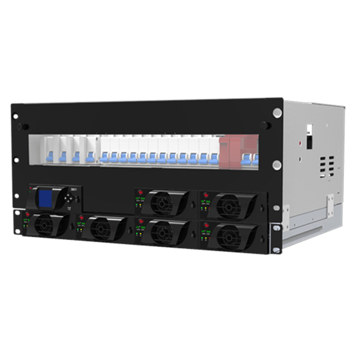
An industrial system solution configured to project conditions for critical-power applications.
18 kW · 48 VDCProduct details →
Product description The 48 VDC Telecom Rectifier provides reliable DC power for telecommunications infrastructure. It converts AC mains power into a controlled, regulated 48 VDC supply for telecom equipment and manages charging of the connected battery bank. Its modular design allows capacity to scale with demand and supports service continuity during maintenance. Parallel rectifier modules provide load sharing and redundancy for high availability in critical communications systems. Digital monitoring and control allow output voltage, current, system status and alarms to be tracked. Remote monitoring and communication options can be integrated according to the application. The compact 19-inch rack design integrates into telecom cabinets and standard equipment racks.
3kW N+1Product details →PRODUCT AND TECHNOLOGY
Parallel, field-replaceable power modules form a scalable DC power system with a controller, AC input, DC bus, battery connection and output distribution.
Each module converts AC energy into a regulated DC output. The controller manages module load sharing, the battery charging regime, alarms and remote communications.
Hot-swap modules reduce maintenance time. Fans, filters, connections, control software and battery performance are monitored at planned intervals.
APPLICATIONS
TYPICAL OPTIONS
Values and options are for initial selection. Final values are determined after the selected product, manufacturer data, specification and site conditions have been verified.
SYSTEM ARCHITECTURE
COMPARISON
PROJECT INPUTS
Unknown values can be clarified through site inspection and engineering before quotation.
AC input and nominal DC voltage
Continuous and transient load currents
Battery type, capacity and recharge time
Required redundancy and communication
Rack/cabinet, IP rating and cable-entry conditions
TECHNICAL QUESTIONS
It allows capacity expansion, redundancy and servicing to be managed at individual power-module level.
It is the Enetek Moduflex+ 5U 18 kW 48 VDC Power Core system. The module count and configuration offered are determined by project requirements.