Product description
A heavy-duty DC system combining an isolation transformer, thyristor rectifier bridge, filter, control, battery connection and distribution in a project-specific industrial cabinet.
 Request a quoteTR
In conventional industrial rectifiers, a thyristor-controlled power stage, isolation transformer, filter, DC distribution and battery management are combined in a project-specific cabinet.
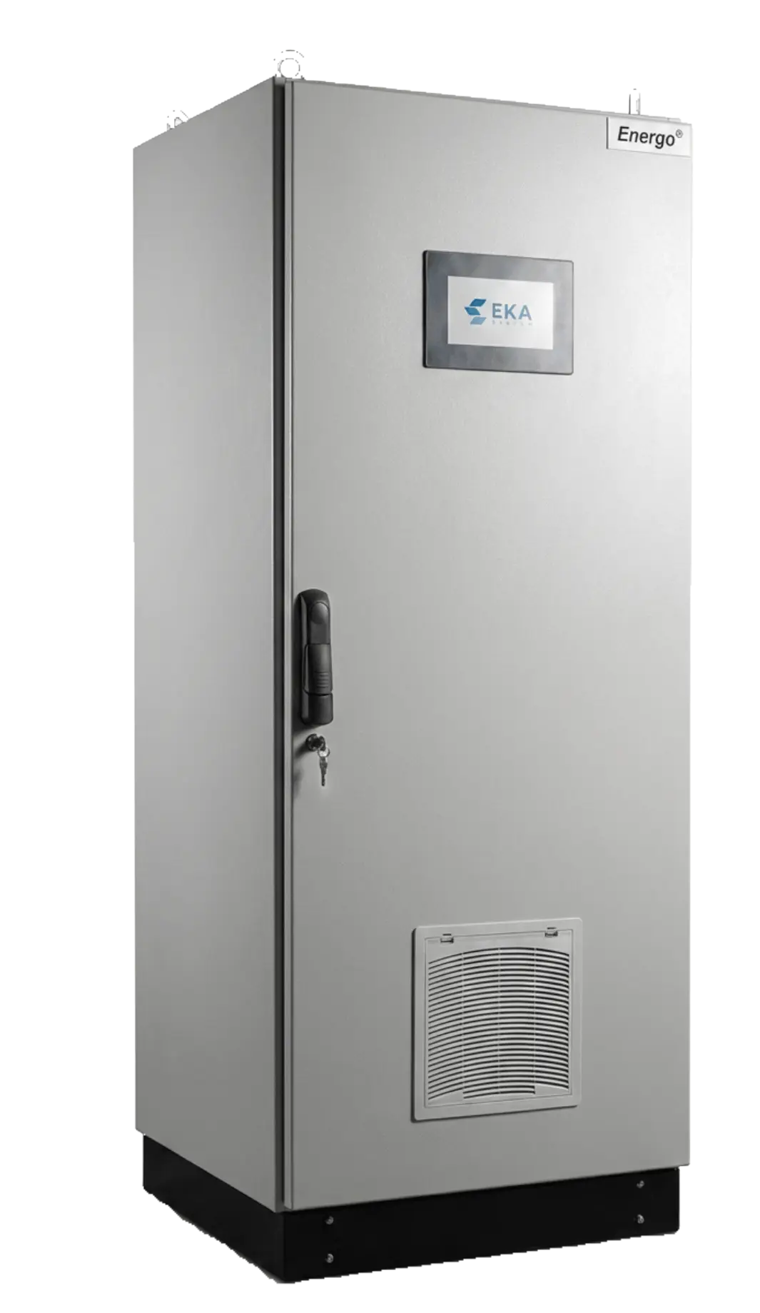
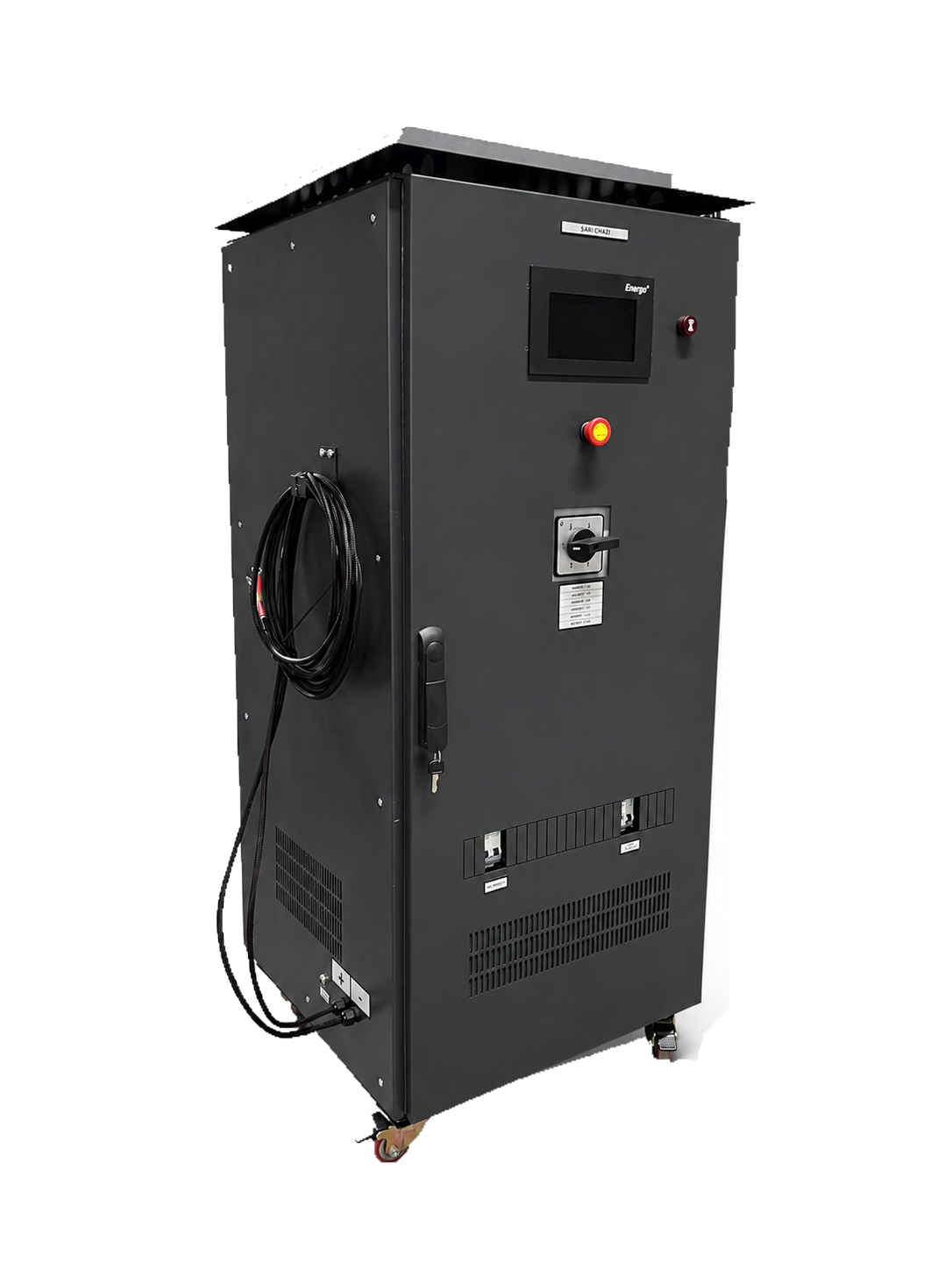
With a 230 VAC input, adjustable 0–160 VDC output and maximum output current of 44 A, the Stepped Constant-Current Battery Charger is designed to charge industrial battery banks reliably using controlled, application-specific parameters.
0-160V 44AProduct details →PRODUCT AND TECHNOLOGY
A heavy-duty DC system combining an isolation transformer, thyristor rectifier bridge, filter, control, battery connection and distribution in a project-specific industrial cabinet.
AC voltage is adapted and isolated by the transformer, then rectified by the thyristor bridge. Firing angle and filtering control the DC bus and battery charging voltage.
Transformers, power semiconductors, capacitors, fans, connections and calibration values are checked periodically. A spare-parts plan is established for critical components.
APPLICATIONS
TYPICAL OPTIONS
Values and options are for initial selection. Final values are determined after the selected product, manufacturer data, specification and site conditions have been verified.
SYSTEM ARCHITECTURE
COMPARISON
PROJECT INPUTS
Unknown values can be clarified through site inspection and engineering before quotation.
Mains voltage, phase and tolerance
DC load profile and coil/motor transients
Battery chemistry, cell count and capacity
Ripple, isolation and environmental requirements
Distribution, selectivity and cabinet requirements
TECHNICAL QUESTIONS
It is a strong option where high power, galvanic isolation, demanding site conditions and long service life are priorities.
The power stage is generally centralised and project-specific within a cabinet. A modular system builds capacity using hot-swap modules.