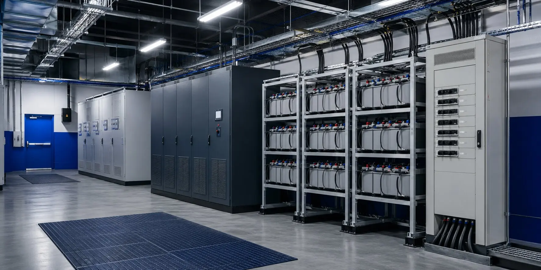
Facility solutions that classify automation, control and auxiliary loads according to their effect on production stoppages and assign them to suitable AC/DC power layers.
The appropriate architecture is defined by critical functions, load behaviour, maintenance paths and site conditions, as well as equipment ratings.
Power-continuity requirements
Reduce the effect of unplanned outages on critical control systems
Operate old and new power infrastructure together through a controlled transition
Plan modular capacity for expanding production lines
Use bypass and distribution arrangements that reduce maintenance risk
Critical loads
PLC, DCS and automation networks
Control computers and industrial servers
Measurement, quality and safety systems
Critical contactors, valves and DC control circuits
PROPOSED ARCHITECTURE
A traceable chain from source to critical load.
Grid/generator
Central UPS and DC system
Distribution by criticality
Local supply points
Automation and process loads
This diagram shows a typical solution approach. Final topology is established using the load list, single-failure criteria, operating philosophy and approved project data.
ENGINEERING DECISIONS
Redundancy, protection and monitoring are assessed together.
Redundancy strategy
Separate critical, controlled-shutdown and non-critical loads
Parallel UPS or N+1 rectifier options
Maintenance bypass and production-line segmentation
Protection strategy
Short-circuit and selectivity calculations
Transient checks for motors, drives and rectifier loads
Earthing, neutral and DC polarity strategy
Control and monitoring
Energy, loading and alarm monitoring
Feed battery and UPS health data into maintenance planning
Status and event information for facility automation
PROJECT INPUTS
What information is required for correct selection?
Share the information available at the initial quotation stage. Outstanding technical data can be clarified during the site survey and engineering review.
Critical-load inventory and impact of downtime
kW, kVA, power-factor and starting information
Existing UPS/DC infrastructure and single-line diagrams
Generator capacity and transfer scenarios
Expansion, maintenance and autonomy targets
EKA DELIVERY SCOPE
Defined responsibilities from calculation to commissioning.
Critical-load classification
UPS/DC capacity and architecture calculations
Distribution, bypass and monitoring solutions
Modernisation and transition plans
FAT — factory acceptance testing
Nominal and transient-load functions
Bypass, alarm and source-transfer scenarios
Panel and connection checks
Document and software-parameter verification
SAT and commissioning
Existing-system interface checks
Load-transfer and outage scenarios
Observe generator/UPS operation together
Operator training and commissioning report
Discuss your facility’s requirements.
Share the critical-load list, autonomy target and existing power architecture with our engineering team.