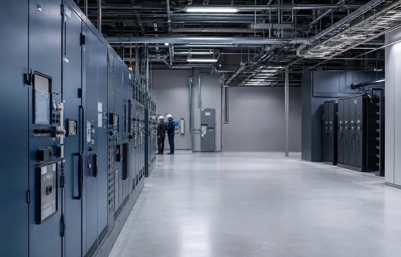
Robust, traceable critical-power systems with planned maintenance, assessing control, emergency-shutdown and communications loads together with process risks.
The appropriate architecture is defined by critical functions, load behaviour, maintenance paths and site conditions, as well as equipment ratings.
Power-continuity requirements
Preserve emergency shutdown and process control during power loss
Provide visibility at remote or hard-to-access sites
Limit operational risk during maintenance and replacement
Assess site classification and environmental conditions using project data
Critical loads
ESD, DCS and PLC systems
Fire and gas detection and security
Telecommunications, radio and field communications
Critical valves, actuators and auxiliary control loads
PROPOSED ARCHITECTURE
A traceable chain from source to critical load.
Normal/emergency AC source
Rectifier/UPS and battery
Redundant critical busbars
AC/DC distribution
ESD, DCS and field loads
This diagram shows a typical solution approach. Final topology is established using the load list, single-failure criteria, operating philosophy and approved project data.
ENGINEERING DECISIONS
Redundancy, protection and monitoring are assessed together.
Redundancy strategy
Separate A/B sources and busbars according to critical functions
Select capacity and redundancy at rectifier or UPS level
Define maintenance-bypass and single-failure scenarios in advance
Protection strategy
Source, busbar and feeder selectivity
Appropriate isolation and interruption in battery and DC circuits
Enclosure, ventilation and access arrangements suited to site conditions
Control and monitoring
Common alarms and detailed event records
Battery-string, busbar and feeder measurements
Approved signal and communications lists for DCS/SCADA
PROJECT INPUTS
What information is required for correct selection?
Share the information available at the initial quotation stage. Outstanding technical data can be clarified during the site survey and engineering review.
Critical process loads and shutdown philosophy
AC/DC load profile and autonomy target
Hazardous-area boundaries and equipment layout
Ambient temperature, corrosion and ventilation conditions
DCS/SCADA interface and acceptance matrix
EKA DELIVERY SCOPE
Defined responsibilities from calculation to commissioning.
System architecture and calculations
Enclosures/panels, batteries and power equipment
Interface, alarm and terminal documentation
Installation supervision and operational training
FAT — factory acceptance testing
I/O and alarm-matrix testing
Source-loss, bypass and redundancy scenarios
Protection, measurement and mechanical checks
Approved test procedures and records
SAT and commissioning
Site interface and cable checks
DCS/SCADA signal verification
Controlled testing of real operating scenarios
Commissioning documentation and user training
Discuss your facility’s requirements.
Share the critical-load list, autonomy target and existing power architecture with our engineering team.